
The coalfired power plant Figure 1 shows the process flow diagram of the coalfired power plant. The basis of the analysed coalfired power plant is provided by the concept study “Reference power plant North RhineWestphalia†[1] which currently presents the stateoftheart of hard coalfired power plants in Germany with a net ...
WhatsApp: +86 18838072829
Process Flow Diagram Process Flow Diagram (PFD) is a drawing which describesthe process flow for a processing plant. PFD is used to capture the main process equipment ... White Rose comprises a new coalfired ultrasupercritical Oxy Power Plant (OPP) of up to 448 MWe (gross) and a Transport and Storage (TS) network that will transfer the ...
WhatsApp: +86 18838072829
Want to continue learning about engineering with videos like this one? Then visit:https:/// Want to teach/instruct with the 3D models shown...
WhatsApp: +86 18838072829
This is the simplified energy flow diagram of the coal fired power plant. Coal is a. flammable black hard rock used as a solid fossil fuel. It is made up of 65 95 % carbon and also. contains hydrogen, sulfur, oxygen and nitrogen. Therefore having a stored chemical energy on. itself.
WhatsApp: +86 18838072829
A process flow diagram (PFD) is a diagram commonly used in chemical and process engineering to indicate the general flow of plant processes and equipment. ... Water cycles of a coal fired power station Electrical energy distribution in a coal fired power plant Sankey diagram. Birds PointNew Madrid Flow Energy Flow Trends 2002 Energy ...
WhatsApp: +86 18838072829
Flow diagram of the coal fired power plant | Download Scientific Diagram Fig 5 Content may be subject to copyright. Flow diagram of the coal fired power plant Source publication +3...
WhatsApp: +86 18838072829
... schematic flow diagram of a pulverized coalfired power plant is presented in Figure 1. The power plantʹs operation can be explained in two, airflue gas cycle and...
WhatsApp: +86 18838072829![Schematic diagram of a coalfired steam power plant [11]. ResearchGate](/qwitz92/405.jpg)
The fossil fuel employed in a steam turbine plant can be pulverized coal (PC), oil, or natural gas. Of these, coal is the most abundant and hence the most commonly used fuel for steam turbine ...
WhatsApp: +86 18838072829
Process flow diagram of the coalfired power plant (sampling port location is marked). Source publication +5 Investigation of aerosol and gas emissions from a coalfired power...
WhatsApp: +86 18838072829
The IGCC plants operate at above 45% efficiency, and CO 2 emissions can be decreased by up to 36% compared with traditional coal combustion power plants [24,25]. It is widely accepted that IGCC technology offers low emission coalfired power generation. The critical challenge of IGCC technology is its high capital cost.
WhatsApp: +86 18838072829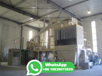
Coalfired power plant with postcombustion CO 2 capture plant model development and incorporated with a neural network inverse control system: Simulation scenarios of power set point variations were simulated showing that fluegas and steam extraction for the reboiler is the most crucial interaction between the two plants.
WhatsApp: +86 18838072829
Figure 1. A coal fired power plant in England. [1] Note the two tall smoke stacks where the combustion products go into the atmosphere and the shorter, wider cooling towers. Coal fired power plants also known as coal fired power stations are facilities that burn coal to make steam in order to generate electricity.
WhatsApp: +86 18838072829
This paper investigates the potential performance of a coalfired power plant based on a supercritical CO 2 Brayton cycle and a postcombustion aminebased CO 2 capture process. An overall flow diagram of the plant is proposed and a simplified preliminary economic analysis is performed. 2. Adaptation of supercritical CO 2 Brayton cycle to coal ...
WhatsApp: +86 18838072829
Context 1 ... a costbenefit analysis will be undertaken considering the effect that the cooling tower has on the thermal cycle of the plant. Figure 6 shows, in a simplified way, how the...
WhatsApp: +86 18838072829
As the present study is focused on coalfired power plants, the performance of these kinds of power plants based on the energy and exergy viewpoints are sought in more detail here ... Process flow diagram of the considered power plant. Download : Download highres image (652KB) Download : Download fullsize image;
WhatsApp: +86 18838072829
Before flue gas desulfurization was installed, the emissions from the Four Corners Generating Station in New Mexico contained a significant amount of sulfur dioxide. The G. G. Allen Steam Station scrubber (North Carolina). Fluegas desulfurization (FGD) is a set of technologies used to remove sulfur dioxide (SO 2) from exhaust flue gases of fossilfuel power plants, and from the emissions of ...
WhatsApp: +86 18838072829
2. Process description of a coalfired power plant. A coalfired power plant burns coal to produce electricity. In a typical coalfired plant, there are pulverisers to mill the coal to a fine powder for burning in a combustion chamber of the boiler. The heat produced from the burning of the coal generates steam at high temperature and pressure.
WhatsApp: +86 18838072829
In both cases a power source is used to turn a propellerlike piece called a turbine, which then turns a metal shaft in an electric generator, which is the motor that produces electricity. A coalfired power plant uses steam to turn the turbine blades; whereas a hydroelectric plant uses falling water to turn the turbine. The results are the same.
WhatsApp: +86 18838072829
In the present study, Unit 1 of Manjung Coal Fired power plant located in Malaysia is considered for investigation. The process flow diagram (PFD) of this power plant is illustrated in Figure 1. To analyze the complete cycle of the power plant, the continuity, energy and exergy equations governing various components of the cycle are
WhatsApp: +86 18838072829
The process flow diagram of a PCC plant is shown in Figure 1. The flue gas enters the plant through a flue gas cooler where it is cooled to temperatures around 35 °C. ... Modeling and simulation of the startup process of coal fired power plants with postcombustion CO2 capture. International Journal of Greenhouse Gas Control 2019, 87, 4457 ...
WhatsApp: +86 18838072829
Biomass power process flow diagram ..... 2 Figure 2. Average EMC for woody biomass in various locations ..... 13 Figure 3. Example monthly energy output for a theoretical 60 MW biomass power plant ... Biomass power plants are very similar in operation to coalfired power plants, as illustrated in Figure 1. The biomass is delivered to the ...
WhatsApp: +86 18838072829
By using the MATLAB calculation tool, a processbased computer program of the coalfired power plant has been successfully validated for thermal efficiency, steam flow rate and coal consumption ...
WhatsApp: +86 18838072829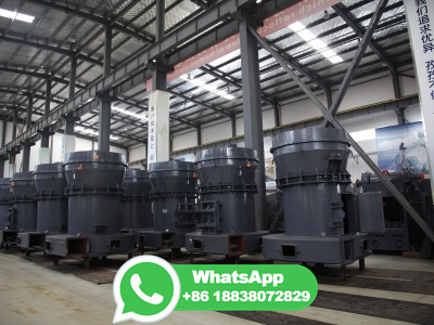
Coal and oilfired process. Coal and oilfired steam power plants have steam turbines to convert the heat energy of combustion into mechanical energy, which then operates an electric generator. All plants use the steam turbine for the drop between the high pressure and temperature of the steam and the lower pressure of condensing vapor.
WhatsApp: +86 18838072829
Main Assumptions: Coal flowrate is a function of the plant load, the coal HHV is fixed and heat dutty from fire side to water wall and platen superheater are fixed. Boiler heat exchanger network: Water Flow: Fresh water > FWH's > Economizer > Water Wall > Primary SH > Platen SH > Finishing Superheate > HP Turbine > Reheater > IP Turbine
WhatsApp: +86 18838072829
However, conceptual baseline analyses prepared by NETL in 2022 assuming use of the Shell CANSOLV CO 2 capture process (designed to recover highpurity CO 2 from low pressure streams that contain O 2, such as flue gas from coalfired power plants, combustion turbine exhaust gas, and other waste gases) would raise the levelized cost of ...
WhatsApp: +86 18838072829
Fossil fuel thermal power plants account for about 40% of total CO 2 emission, and coalfired power plants are the major contributor [1]. Global warming has become a significant research issue along with more and more international attention [2]. ... Process flow diagram. According to the introduction above, most of the LNG related cryogenic ...
WhatsApp: +86 18838072829
The process flow diagram and a photo of the system are shown. ... The solution depicted in Figure 6 is that of a typical wastewater from a coalfired power plant wet FGD system. After evaporation ...
WhatsApp: +86 18838072829
A material supplier from Belgium would like to produce limestone powder for his custome...

India is rich in various mineral resources and it is an important mineral processing market
Copyright © 2023 GMC Co., Ltd. SiteMap

